Mechanical UT Scanner
When I was busy looking for work in the USA after building a software and mechatronics in Cape Town for the passed 3 years, I didn’t have much of a mechanical-engineering oriented portfolio to show during potential interviews. The reality was that most of my free time was spent upskilling in software and architecture design and mechatronics and boring stuff like ISO 9001 audits.
I’ve spent a large part of my career building and thinking about how to improve in-line inspection robotic tools. Like the difficulty of saying that sentence quickly five times, there are a lot of interesting and difficult challenges that these tools introduce. For one, there is a constant competing real estate for the central axis between the centralizing, rotation, and transport (in terms of fluids and electronics) mechanisms.
This request came at a time when I had been entertaining the idea that you could exploit the relationship between the axial movement of the tool through the pipe, and turn it into rotational movement of ultrasonic probes to scan the pipe. It’s an interesting idea that quickly becomes unstuck: you have rotating probes that require a water and electrical supply, but you also need a way to track the position of the tool in the pipe with electronics. This means that you’d need a hybrid rotary union of high-frequency electrical connections and water supply, which they don’t sell at Walmart. So you’d be looking at expensive custom solutions - defeating the purpose of removing the electric motor to simplify and cheapen the tool. But that’s what makes this a great project to choose, since there’s no risk of me leaking company IP, and would allow me to expose my thoughts, reasoning, and mistakes to the hiring manager.
Considering this, I wanted to give myself a week (of evenings & weekends) to complete this project since that’s all of the free time I was willing to commit to this. So let’s decide some project specifications so we can determine if ultimately it is a success or failure.
Project goals:
- Figure out if we can use the travel to spin the probe axis
Scope:
- Focus on the mechanical design in detail, make sure it’s possible to manufacture and assemble (cheaply and easily)
- Will ignore vibrations and things like variation in the pipe ID (since these are relatively easy to consider later)
Constraints:
- Can we do it in one week.
Project specifications:
- The pipe to scan is carbon steel
- Needs to scan 100% of wall thickness surface area (since that’s where the O&G industry is moving towards)
- The pipe diameter does not change and is known beforehand
- Needs to be cheap and easy to make
- Needs to be light enough for a person to carry (<45 lbs)
- Needs to be easy to repair or replace broken components
- Needs to operate in harsh conditions
Considering these above goals, specifications, and constraints, our approach is important so we focus on making progress and don’t get stuck into analysis paralysis. Especially considering that the general idea is bad, there will be a lot of choices between bad and worse decisions, but it’s important to push ahead so we can iterate quickly.
After reviewing existing designs and seeing if there are any ideas we can /steal/ reverse-engineer, we can begin some initial sketches. There basically are 2 ways to centralize the tool:
- We can force the wheels outwards
- We can have the main body of the tool sit low and have a raised axis to centralize the probes
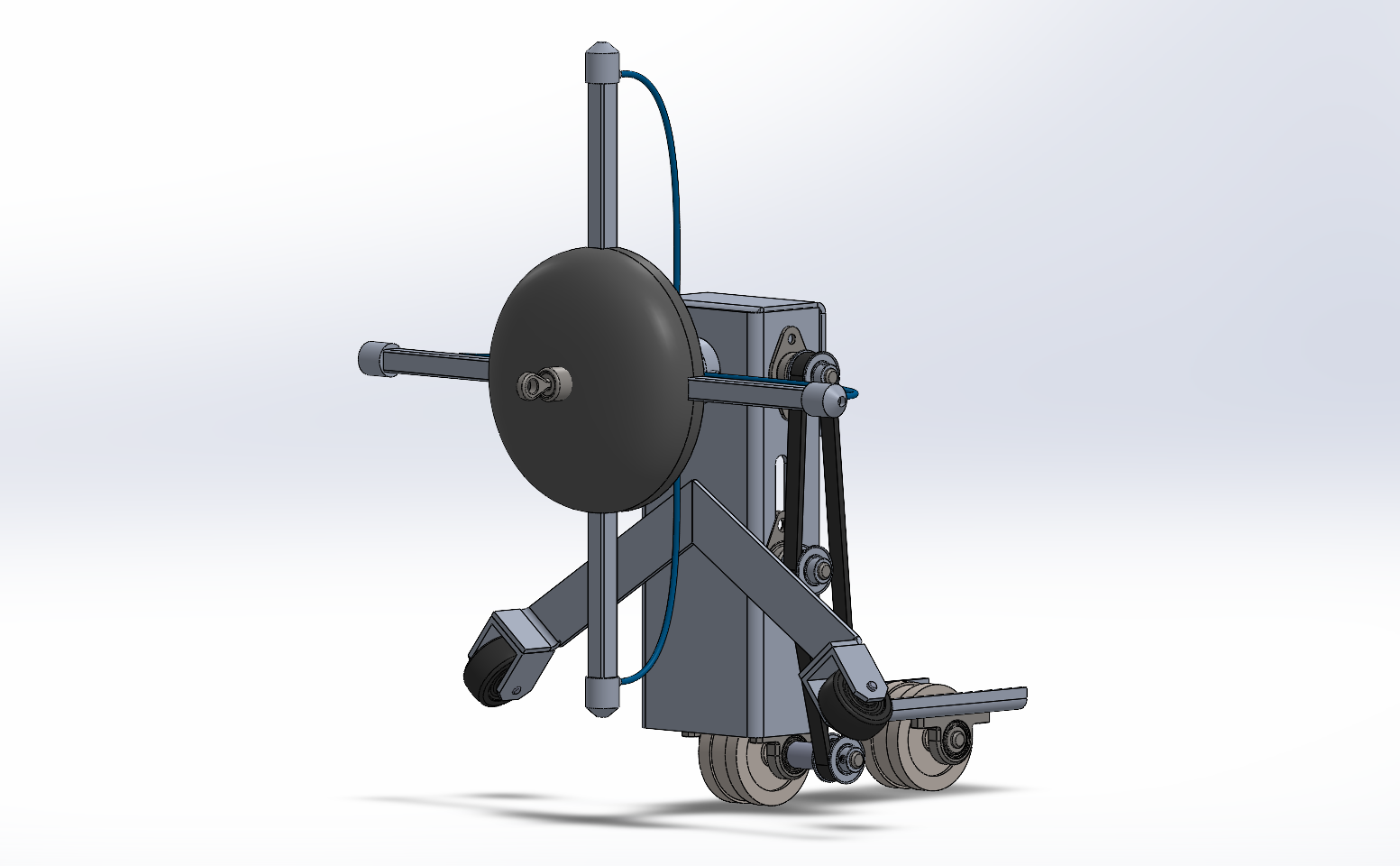
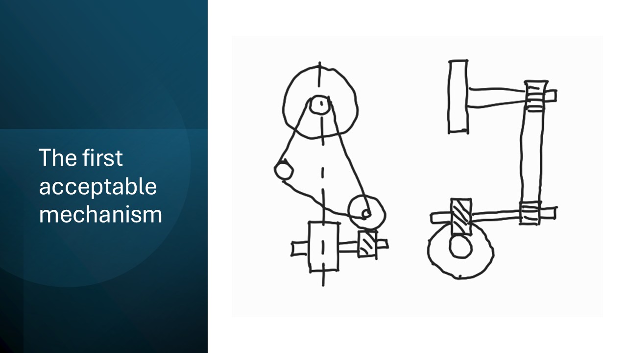
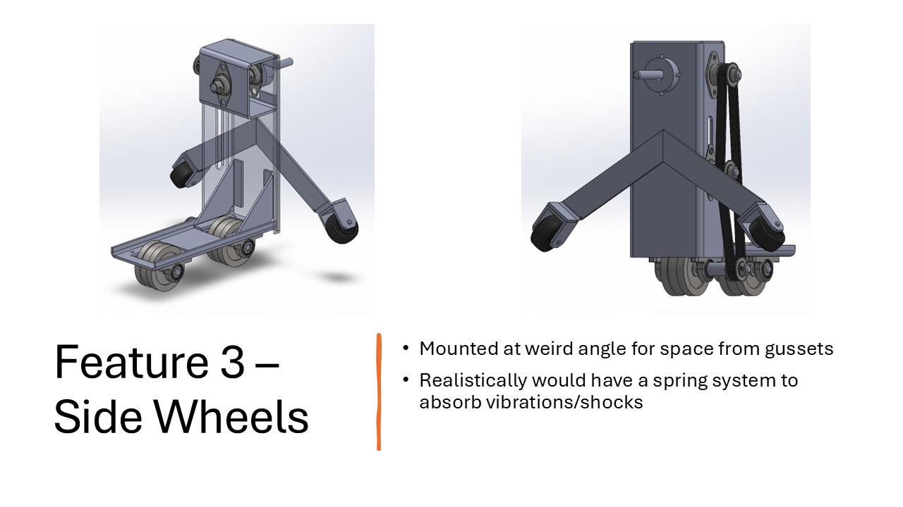
Keeping the main thing, the rotation mechanism, in mind - it’s inherently more difficult to implement a solution that uses centralizing legs since these legs are not fixed and therefore any transfer of power would be complicated. Considering you’d want some sort of magnetic wheel to increase the normal force and reduce chance of slippage, I went ahead with the crawler design. This feels like the right idea since we won’t need all the extra weight of centralizing leg linkages. After iterating mechanisms, the below one was the first one I was marginally happy with. We’re under the gun so let’s push ahead and, as the youths say, mess around and find out.
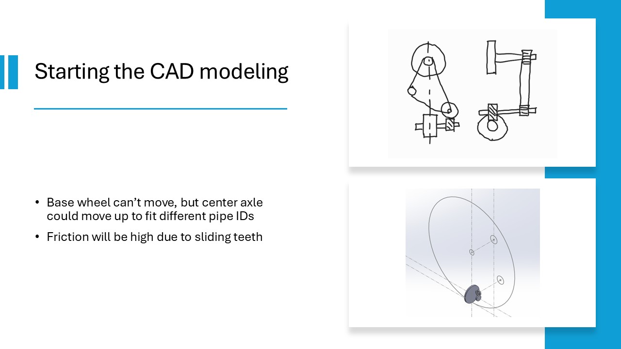
Starting the CAD Modeling
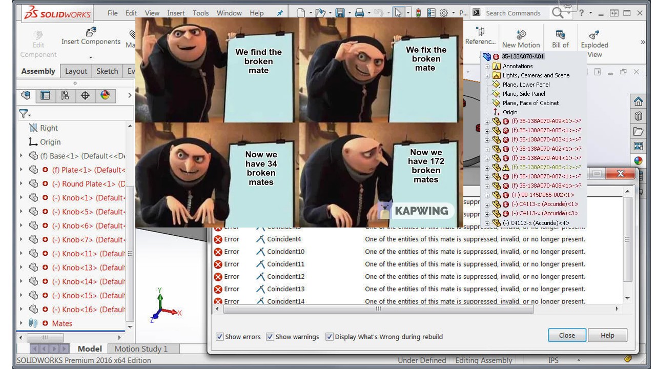
Because we’re in such an early design phase, we’re going to use a top-down modeling method, specifically using a “Master Model” that we can derive assemblies and parts from so that it’s easier to make sweeting changes and move things around. Interestingly enough this reminded be a lot of moving software around between classes. It’s always great to find links between different disciplines (like how fluid pressure is a great metaphor for electrical voltage). Although with software it’s much easier to move code around - the compiler will warn you of any mistakes and they can usually be fixed in a couple of clicks. SolidWorks however is like an old stubborn grandpa, who after telling him you’re going to move the TV remote out of the kitchen utensil drawer, he’ll forget and have a fit when he can no longer find it.
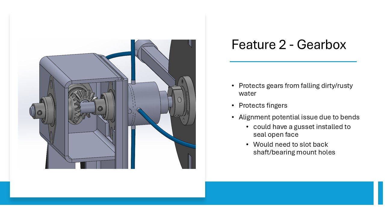
After modeling the basic mechanism, it quickly became apparent that the 90-degree helical gears would cause a lot of friction due to the sliding of the teeth against each other. Friction is our biggest enemy in this project so we’re going to have to come up with a better solution. The other enemy is cost, and this setup would likely require a custom gearbox to house the grease in to lubricate the gears and keep dirt and contaminants out.
Which brings us to the second iteration, which addresses the main issue with the first design by swapping to miter gears and moving the pulleys to the side. There will significantly less tooth-sliding and therefore less friction in this design. But now the nest issue that’s glaring is the alignment of the back wheels.
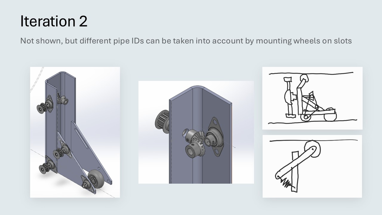
This iteration introduces the main frame which is made of bend aluminum sheet metal. The flanged sides will add rigidity by increasing the second moment of inertia. Sheet metal parts are cheap to manufacture but there is always an error tolerance to each bend - it will never be perfect. You can help address this by adding gussets or laser cutting slots and tabs to better align parts, but for this current design, there is too much possible flexion of the back wheel. The issue is that even if the rear axle is off by one degree, it would essentially act like a turning wheel and cause the robot to corkscrew in the pipe and topple over. Not ideal.
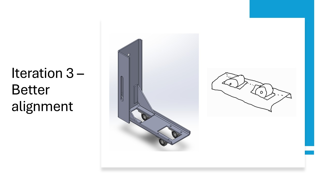
We can scrap that frame idea and go back to the drawing board for the base. We’ll make it out of one piece of sheet metal to ensure precision of the wheels, still bending the sides slightly for strength. This looks and feels better, and gives us the perfect space to mount gussets to secure the base to the main frame. There is also a nice flat area in the middle of the base where we could add cross-braces to the main frame to better support it if needed. This kind of flexibility in design even after a component is made is ideal when iterating a design quickly.
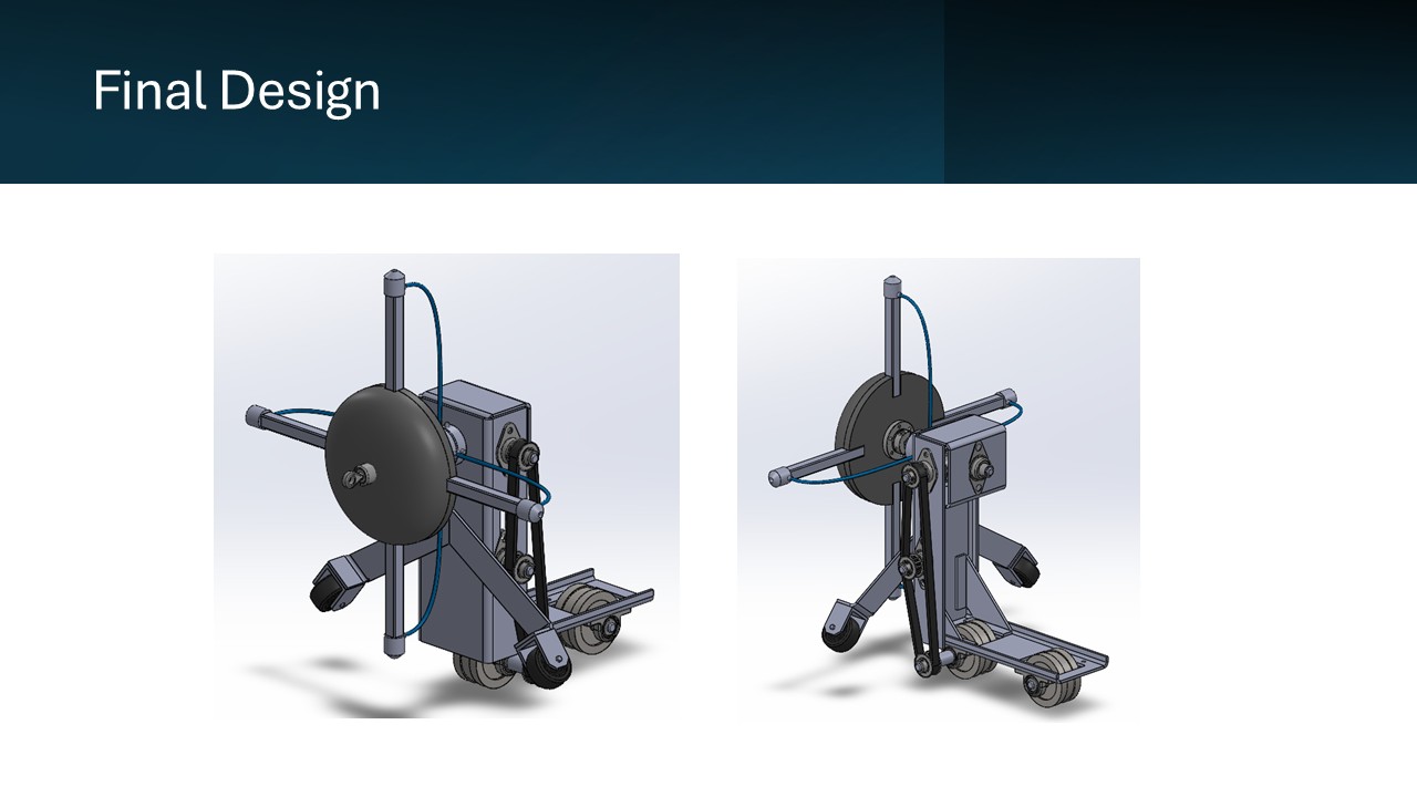
Now that all the main problems are addressed, we can focus on modeling the final robot. At this point, I had a good enough idea of the design to be able to calculate how much friction would be in the system to answer our initial question, but let’s not ruin the surprise. Here is the final design, you’ll notice fasteners have been left out due to time and will constraints.
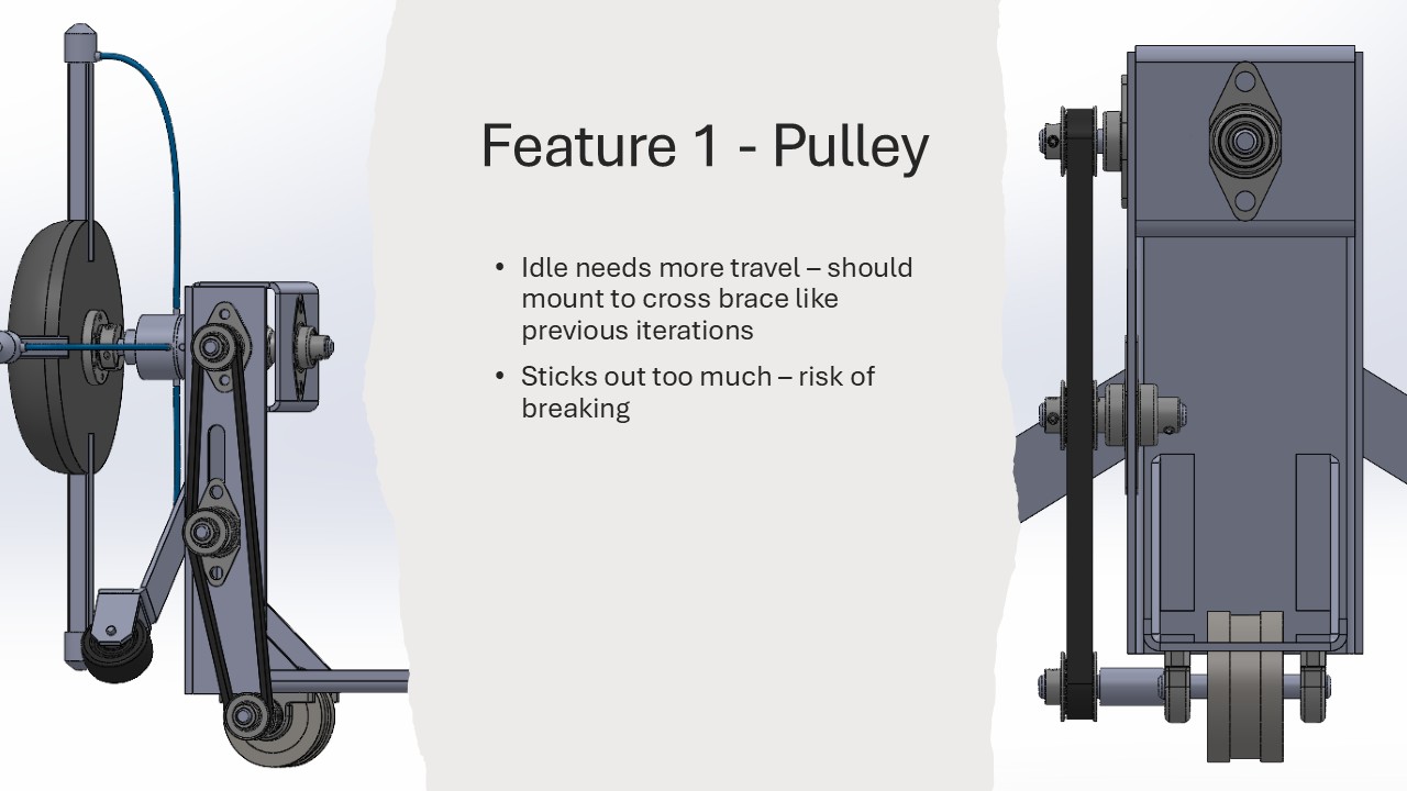
To go feature by feature and discuss the design:
Will it work?
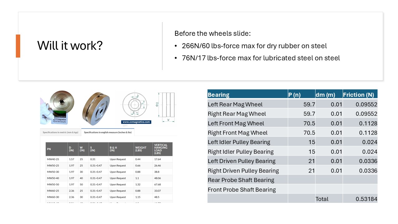
Ultimately the system will be unable to spin if there is slipping of the wheels. This would happen if the max frictional force is less than the force needed to spin the wheels. With the robot designed, we can see it has an estimated weight of between 15-18 lbs. Using this we can see that there is a max friction force of 266N/60 lbs-force for dry rubber on steel (if the magnetic wheels were coated) and 76NN/17 lbs-force if it was lubricated steel on steel (due to residual grease or oil in the pipes.)
Now we need to calculate total friction – this will be the limiting factor This is done by summing all the friction in the drivetrain i.e. bearings, gears, and pulleys Bearing friction = starting torque = sliding frictional moment + frictional moment of the seals Sliding frictional moment = M = 0,5 x μ x P x dm Where μ is 0.08 – 0.2 for lubricated steel on steel ball bearing
So basically we have to do force balance and bending moment diagrams of each shaft to predict the normal force on it. This is shown in the table below. We’ve left out probe shaft bearings since they will require angular contact bearings to properly distribute the axial force on the shaft from the robot being pulled, which complicates the design. And at this stage I had pretty much run out of time and looking at the below values compared to the max it would be needed to cause slipping calculated earlier, it’s reasonable enough to make an educated assumption that this mechanism would work.
So in summation:
The bad:
- Awkward shape – risk of damaging pulley/probes
- Requiring it to be pulled adds an extra man/labor cost
- Realistically would never get approval due to indirect location tracking
The good:
- The mechanism should work, it’s possible
- Very light compared to general inline inspection robots: 15-18 lbs.
This was a fun project and I think impressive for the level of detail achieved in the short space of time. In terms of lessons learnt, the biggest is simply that a better design is needed to not have to pull the robot on a bearing swivel or house the electronics along with the spinning probes. During presenting the project, someone had a good idea of pulling the robot backwards, which would alleviate concerns of the robot being pulled over and breaking the probes.